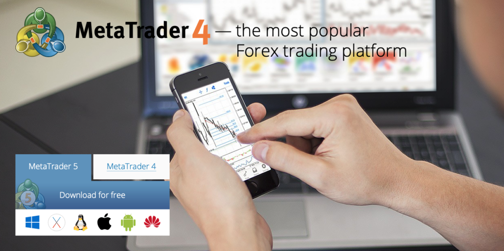
MetaTrader 4 (periodically abbreviated to “MT4”) is a prominent trading platform formulated by MetaQuotes Software. The first interpretation of this interface was broadcast in 2005 and has since been approved by several popular vendors as their major trading interface.
When you are a Binary Options trader, you might ask if it is possible to trade Binary Options on the MetaTrader. In this article, we will give you the answer – Yes, it is possible to trade Binary Options via the MetaTrader, and we will show you how to do it in the next steps!
How to trade Binary Options with the MetaTrader: Follow these steps:
In the next steps, we will show you exactly how to trade Binary Options with the MetaTrader 4 software. Attention: It is only possible via the desktop/pc application of the MetaTrader 4.
- Sign up with the broker WordForex
- Verify your trading account on wforex.com fully
- Create a live trading account or demo account on Core Liquidity Markets
- Download the MetaTrader 4 here
- Download the Binary Options plugin for the MetaTrader
- Login into the MetaTrader 4
- Deposit money into your trading account
- Open a new chart and choose the right symbol to trade Binary Options
- Start trading Binary Options on the MetaTrader!
See the full video tutorial here:

By loading the video, you agree to YouTube’s privacy policy.
Learn more
1. Sign up with WorldForex
Due to our comprehensive research, WorldFOrex is the best of only a few brokers we found which is offering to trade Binary Options via the MetaTrader 4. You can sign up for free for your trading account.

WorldForex is an online broker which exists for more than 8 years. It is a company based in St. Vincent and the Grenadines and the British Virgin Islands. You can trade there more than 100 different assets via forex, CFDs, and Binary Options.
Quick facts about Core Liquidity Markets:
- Broker for more than 15 years
- Binary Options trading is available via the MetaTrader 4
- Personal support
- Minimum deposit of $ 10
- Free demo account
- The high return of up to 90%+
- Minimum trade amount of $ 1
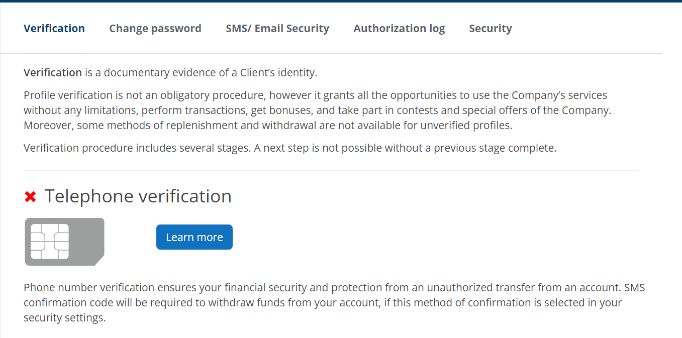
2. Verify your trading account
For trading with real money, you will need to verify your account fully via a personal document and an address verification. See the screenshot below. After the verification, you are able to open live trading accounts or demo accounts in the dashboard.
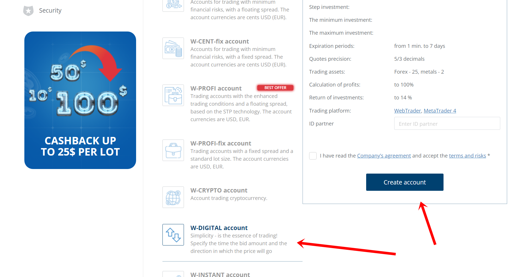
3. Create a new account for MetaTrader trading and Binary Options
Now you have to create a new trading account for the MetaTrader 4. You can decide if it is a euro, dollar, pound, or Australian dollar account.
4. Download the Core Liquidity Markets MetaTrader 4
Download the MetaTrader 4 through this special link here:
https://wforex.com/trade-station/worldforex4setup.exe
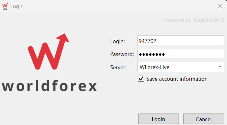
5. Login into the MetaTrader
Now it is time to login into the MetaTrader with your account credentials. Choose the live trading or demo trading server. Also, choose the Core Liquidity Markets MetaTrader.
6. Deposit money into your trading account
In order to trade Binary Options with the MetaTrader, you have to deposit money into the broker’s account. The minimum deposit is only $ 10. The minimum trade amount is $ 5. There are multiple payment options!
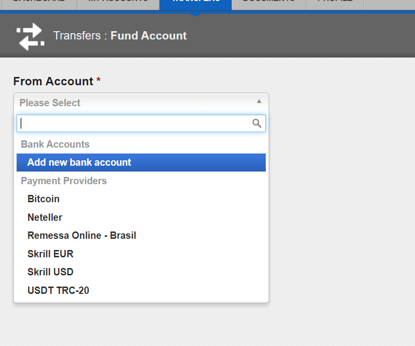
- Bank transfers
- Bitcoin
- Neteller
- Skrill
- Tether
- Local banks
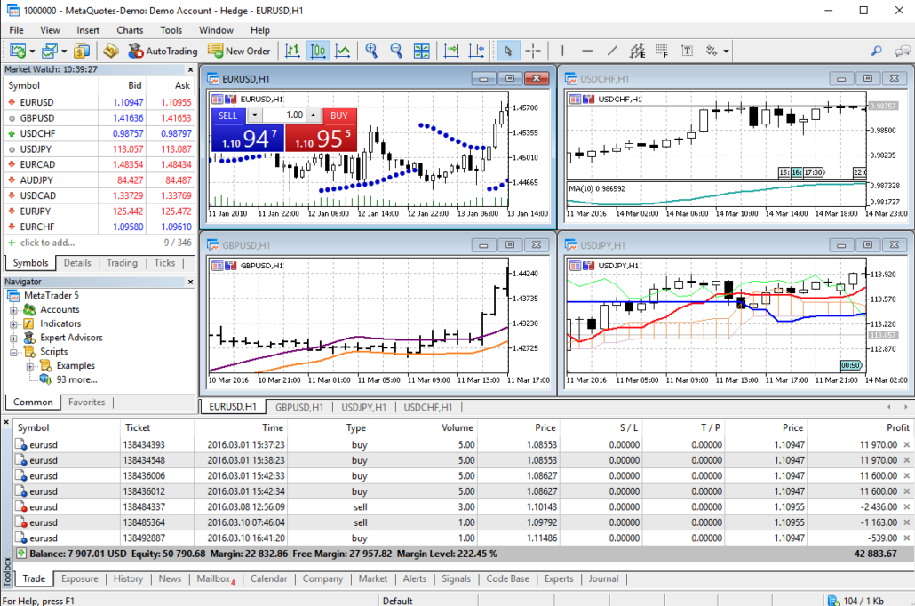
7. Open a new chart and choose the right symbol to trade Binary Options
First of all, you have to click into the terminal on one asset with a right-click an select “show all”. This option will show you all available assets in the MetaTrader.
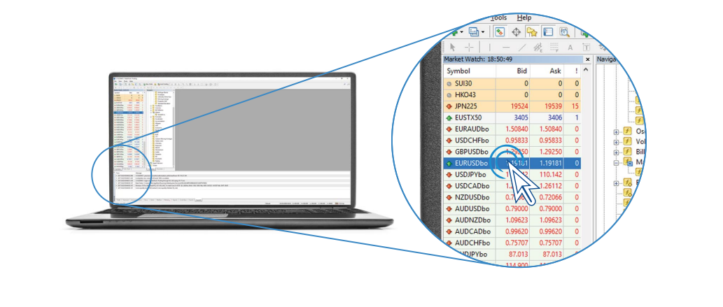
Binary Options charts are called with “bo” on the end of the asset. For the EUR/USD it would be “EURUSDb”. Select the asset and chart you want to trade!
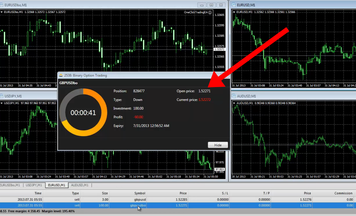
8. Start trading Binary Options on the MetaTrader!
By double-clicking on an asset in the terminal or by clicking “open a new order” in the MetaTrader the trade window will open. You can now start trading Binary Options!
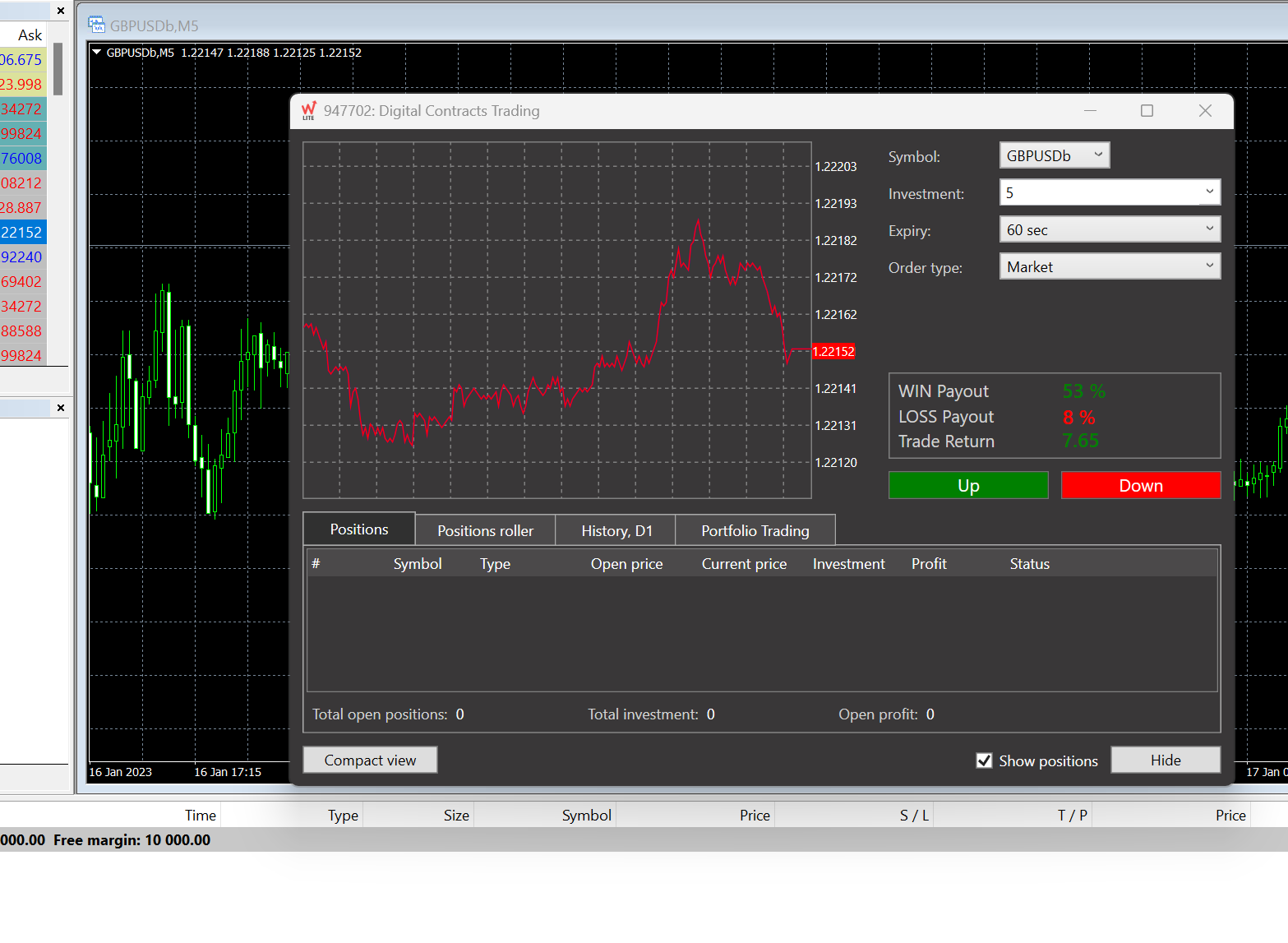
- Select the investment amount (minimum trade amount of $ 5)
- Choose the expiration time
- Choose a market order or pending order
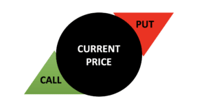
- Use a call or put option
- Wait for the result
That is how easily you can trade Binary Options on the MetaTrader. Just sign up with WorldForex, and you are ready to go!
What is MetaTrader 5?
MetaTrader 5 is not only merely a trading outlet. It is a detailed and highly selected platform that enables vendors to trade the financial market around the nation.
Further, it has a highly vulnerable interface, prosperous functionality, a straightforward and spontaneous trade reason. The outlet MetaTrader was broadcasted in 2010. It is a remodeled as well as an upgraded interpretation of MetaTrader 4.
Thousands of vendors and financial outlets practice this high-tech trading platform. Furthermore, it benefits major financial news providers, which is a significant benefit for vendors. Therefore, binary trading is now susceptible to other outlets.
Why is MetaTrader 5 the market administrator?
Various vendors widely adopt the platform just for its advantages and characteristics. It is the nicest option for new vendors and for progressive traders. You can buy a trading order without leaping into different sites for market analysis because you will learn all the essential devices under one roof.
The following are some of the well-known characteristics of MT5 that make this outlet convenient for vendors:
- Influential trading outlet
- Can entry from any tool
- Vendor’s capital and data will be protected
- User-friendly strategy
- Influential analytical devices
- Large timeframes
- A specialist advisor or auto trading capability
- A broad range of trading tools
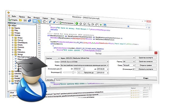
MetaTrader features guide
The MT4 and MT5 platforms are assembled of a few fundamental elements:

- The Navigator: The Navigator authorizes users to search their various accounts, data analysis pointers, expert advisers, and articles. This would primarily be consumed by trading specialists who have numerous accounts with various vendors.
- The Graph Area: Most of the effort will take a position in the entirely customizable graph region. As the term itself signifies, this is the place where you would be eligible to review financial information and analyze tendencies. Nonetheless, some users would choose just to adopt one graph and research it amid data estimation devices.
- The Tool Bar: Probably one of the extensively crucial aspects of the interface to champion, the Tool Bar comprises various valuable components to layout charts, expand modern windows, alter the language, or ensure the recent trading climate.
- The Toolbox: Not to be misinterpreted or misunderstood with the Tool Bar (at the top of the window), the Toolbox is located at the lowermost and would help you to search your recent trades, disclosure, record, mailbox, chart, the popular MT4 market, along with warnings and indications.
By grasping these four building slabs, you will effortlessly and skilfully be eligible to begin trading on MT4 and MT5.
Nevertheless, these two outlets have much more to provide:
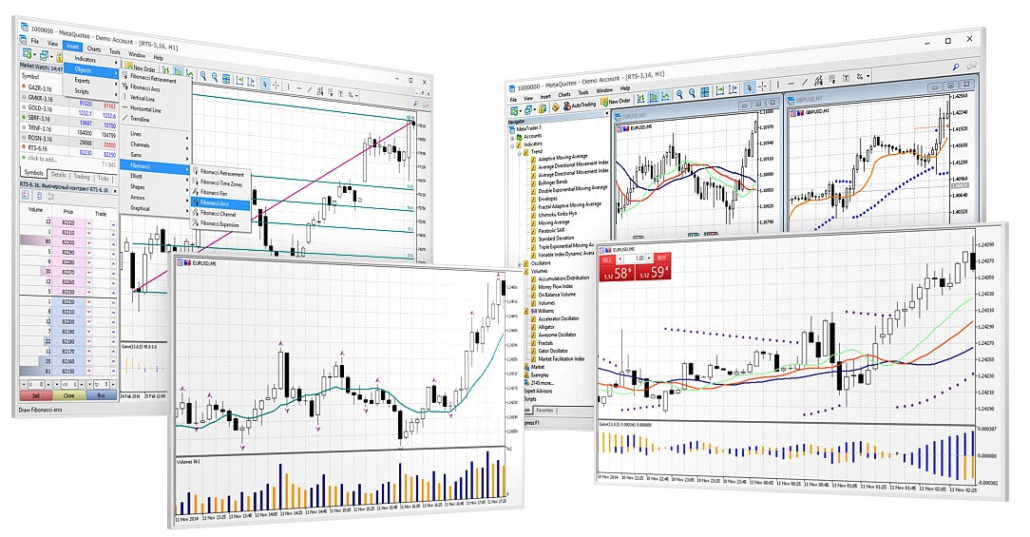
Graphs and Data Estimation Tools
Various vendors clearly cannot function without MT4 and MT5 just because of their progressed data visualization characteristics. Firstly, any chart can be enhanced and lessened shown as a bar diagram, candle stakes, and line diagrams.
Profitable investors also utilize the vast variety of indicators formulated by the MetaTrader platforms. These pointers comprise Trends, Volumes, Bill Williams (pointers formulated by the fictitious dealer Bill Williams), and various supplementary.
Whereas unskilled investors might not completely sense the significance of these mathematical devices, they could be truly beneficial in getting a “feel” of the market and foreseeing prospective price activities.
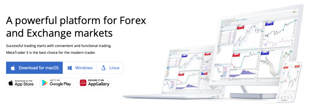
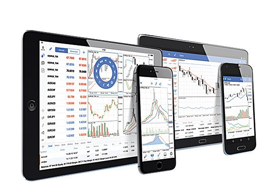
Mobile and Web Trading
MetaTrader Software creators also appreciate that investors should tour and want to be eligible to trade around the world and at any moment. This is the justification for why the MT4 and MT5 outlets are accessible on the application of mobile on Android and iOS tools.
For those investors who choose to trade on a desktop, this trading interface is also accessible on a web version, available from the computer browser.
(Risk warning: Your capital can be at risk)
Automated Trading
The MetaTrader outlet also constrains the strengths of computerized trading in a characteristic known as “Expert Advisors”, which is not insufficient than computerized trading software that will do the work for you. The computerized trading software can furthermore be adapted. This is a very creative device that maximum coding vendors will be eligible to understand.
Benefits and drawbacks of the MetaTrader platforms
- A completely creative diagram and data examination interface
- Endless software chances with add-ons and specialist advisor strategies
- Trading warning signals and social trading to obey the nicest investors on the planet
- Best by test: administrator in online trading software for more than a decade
- A prospering community of vendors and creators
- Flexibility periodically arrives at the expenditure of the rest of the use
- Analysis and workout are essential before completely triumphing the ins and outs of this software
- A rising number of vendors are now regressing to constructing their software
(Risk warning: Your capital can be at risk)
MetaTrader 5 Tutorial: How to practice MT5
The MT5 platform is susceptible to utilize and benefits credible vendors with numerous trading assets. MetaTrader 5 outlet provides a demo account. So, you will get an opportunity to make a short tour before marketing with real wealth.
In one platform, you will glimpse all the main components that are associated with the trading world. For the initial time, you would be required to download the software in your tool. You would also be required to open an account with a reasonable e-mail id and a strong password.
In the menu bar, you would get all the data that will enable you to build a diagram utilizing trading pointers and examination devices. You can also develop a customized trading climate.
Yet, a vendor can unlock numerous trading dashboards to analyze more than one trading asset. For example, on the topmost left side of the dashboard, you would notice a market watch with all actual-time information of selected trading assets.
Likewise, from the toolbox section, you would be able to discern the trading list with open, close, and pending declarations. The prevailing MetaTrader 5 outlet has multi-active windows with all valuable sections like trading signals, market announcements, inner mailbox, professional journals, auto trading, and furthermore.
To place an order utilizing this outlet, you must fulfill the below three easy steps:
- Unlock the market stare area
- Choose the asset and unlock a modern order
- Conclude the kind of order that you expect to perform, moment, pending, or demand order
Get a free deposit bonus of 50% at Quotex with our promotion code “bobroker50“
You can only use this bonus code by signing up via our website.
(Risk warning: Trading involves risks)
Platform overview – Nicest application for dealers
As we have already discussed, a brief opening on the MetaTrader 5 outlet. Globally, it is a critical application where vendors can enter from any tool.
Moreover, the outlet enables you to unlock up to 100 trading diagrams on various trading assets. Thus, the MetaTrader 5 gives vendors impressive, influential, and valuable devices for high-grade understanding. In this stage, we will divide the outlet into several different fractions with the person’s explanation and benefits.
MetaTrader 5 – Trading Indicators
A specialized indicator is an incredibly crucial device when it gets a too technical examination. Technical indicators enable you to recognize several diagrams in the price dynamics of money, shares, and other aspects of monetary tools automatically.
The information gives rise to it simple for vendors to make beliefs about prospective price activities. According to the examination, you can also modify your trading techniques.
There are enough technical indicators, but the great outstanding and prominent MT5 indicators are comprised in MetaTrader 5. It has more than 80 technical indicators accessible with 21 timeframes.
Any vendor can utilize any of these specialized indicators in their trading procedures and techniques. In addition, most technical indicators come with an abundance of settings that facilitates vendors to modify several devices for assignments.
Moreover, vendors can regulate the manifestation of the indicators by logical parameters and settings. For example, the duration of the moving normal will alter along with the thickness, color, and line. Lastly, you can place the ultimate indicator on the rate chart or in the outstanding panes alongside its hierarchy values. Of course, it is feasible to pertain to some other indicators too.
MetaTrader 4 Vs. 5: Which is better?
The exterior interface of MetaTrader 5 has not altered that much. Also, the terms of the menu and icons are like MetaTrader 4, so vendors would be able to get over the software’s slackness rapidly and conveniently.
Furthermore, the impression of the MetaTrader 5 terminal stays like MetaTrader 4. So, the evolution of the modern and updated trading platform will not formulate any enormous difficulties for traders. Nevertheless, there are few crucial architectural modifications accessible between the modern MetaTrader 5 and MetaTrader 4. An additional outstanding and valuable new characteristic is that a mouse can be used for role control.
The Economic Calendar is an effective expansion of the interface also. Now, vendors and dealers do no require to go to numerous websites glancing for a substantial period of circumstances any longer.
Conclusion: Binary Options trading is possible via CLMForex.com and the MetaTrader 4
Examining this article, it fulfills obvious that MT4 and MT5 have governed to maintain their position of overseeing online trading software appreciation to an adequately constructed, ergonomic, and creative platform, as well as an effective community of investors and programmers.
Binary Options trading on the MetaTrader is very rare to find, but when you are searching, you will find a solution like our guide. It is a simple process to use the MetaTrader for Binary Options trading. You just need a broker who is supporting it. Core Liquidity Markets is the best choice!
Most asked questions about Binary Options trading via the MetaTrader:
Is Binary Options trading available via the MetaTrader?
Yes, it is available via the broker Core Liquidity Markets. There are only rare options to trade binary via the MetaTrader. This broker is offering an inbuilt plugin to trade binary options via their MetaTrader
Can I use all tools and indicators of the MetaTrader for Binary Options?
It is possible to use all features of the MetaTrader by trading Binary Options. For example, you can use the indicators, automated trading features, signals, and more to trade Binary Options via the MetaTrader.
How to trade Binary Options on the MetaTrader?
Click on the right symbol which is called for example “EURUSDbo”. After clicking on “new order” a special trade window will open for trading Binary Options. Select the investment amount and expiry time. Then you can choose a put or call option.